Breathing Circuits
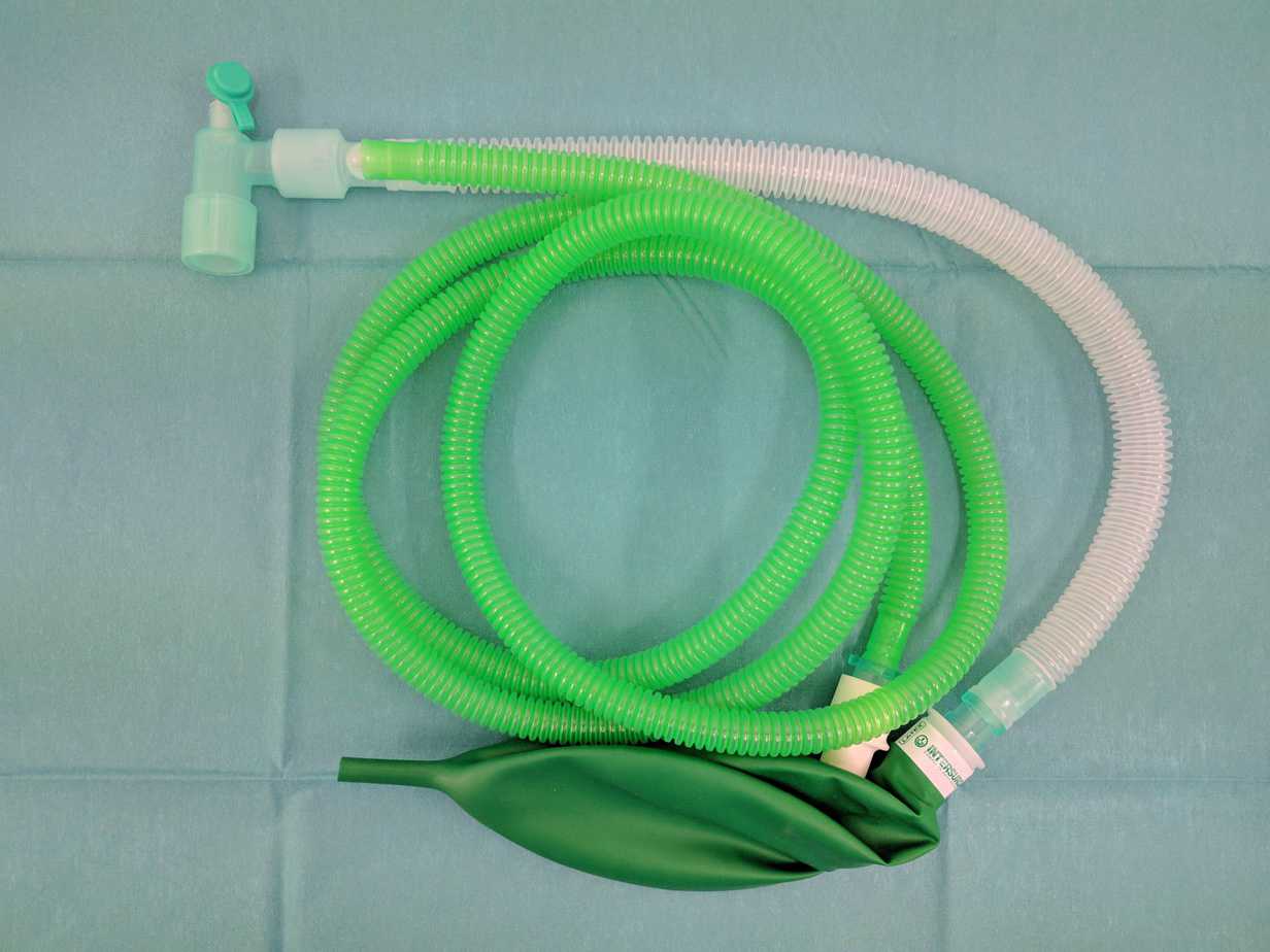
A breathing circuit is simply one or two pieces of plastic tubing and a bag that connect a fresh gas flow (wall oxygen or ventilator) to the patient’s airway i.e face mask, laryngeal mask airway (LMA) or endotracheal tube (ETT).
The breathing circuit has two main functions:
- To carry oxygen and fresh gases e.g. nitrous oxide, nitric oxide or anaesthetic gases, to the patient.
- To carry exhaled carbon dioxide from the alveolar gases away from the patient.
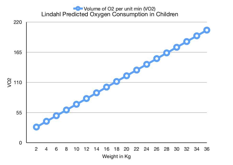
First lets look at oxygenation. The standard formulae for calculating oxygen consumption in infants was determined by Landlahl in 1989.
Predicted Oxygen Consumption = 5.2 x weight + 18.1
It’s therefore safe to assume that a term baby up to 4 kg requires a minimum oxygen flow of 5.2 x 4 +18.1 = 39 mls of oxygen per minute. A 25 kg child requires 5.2 x 25 +18.1 = 148 mls of oxygen per minute. The normal oxygen flow rate to set for the delivery of oxygen starts at 2 litres/minute which far exceeds the oxygen consumption in millilitres per minute of all children and adolescents. As we shall see below the higher flow rates are required to prevent rebreathing of the alveolar gases.
Before the days of carbon dioxide absorbers and even on modern ICU ventilators the fresh gas flow (FGF) must be set to a specific rate in L/min in order to ensure there is no rebreathing of carbon dioxide that a patient exhales with each breath. The amount of rebreathing that occurs with any particular anaesthetic breathing system depends on the following four factors:
- Design of the individual breathing circuit
- Mode of ventilation (spontaneous or controlled)
- Fresh gas flow rate
- Patient’s respiratory pattern
Breathing circuits eliminate rebreathing either by ensuring an adequate flow of fresh gas which flushes the circuit clear of alveolar gas, or, in the case of a circle system, by the use of soda lime, which absorbs the CO2 so that low fresh gas flows may be used. To set the correct rate of fresh gas flow to flush alveolar gas from the circuit requires knowledge of the individual breathing circuit and the minute volume (MV) of the patient. In order to calculate the MV and therefore the FGF correctly we will review a few basic definitions in respiratory physiology.
Tidal Volume (TV) is the volume of air we breath with each normal breath and is recorded in millilitres (mL). It is approximately 5 – 7mL/Kg during normal breathing – called tidal breathing.
Respiratory Rate (RR) is the number of breaths we take in a minute.
The Minute Volume (MV) is the volume of air we breath in and out during normal tidal breathing in a minute of time. It is therefore calculated by multiplying the TV by the RR and is generally quoted in L/min.
Lets examine the breathing circuit. It has:
- An inspiratory limb connected to the FGF at one end
- An expiratory limb with or without an adjustable pressure/blowoff valve
- A rebreathing bag connected at some point along the inspiratory or expiratory limb
- 22mm connector at the patient end
- 15mm connector at the FGF end
Air passes through the FGF, along the inspiratory limb towards the patient. The patient takes a tidal breath and inhales the fresh gases. When the patient exhales, the exhaled alveolar air passes along the expiratory tube. If the FGF is not set to the correct rate, during the next tidal breath when the patient breathes in, some of this alveolar air (containing carbon dioxide) will return to the patient. This is called carbon dioxide rebreathing which has the obvious consequences of increasing carbon dioxide levels in the lungs which will lead to increased carbon dioxide levels in the blood causing a respiratory acidosis. The purpose of setting the FGF correctly is to ensure carbon dioxide rebreathing does not occur.
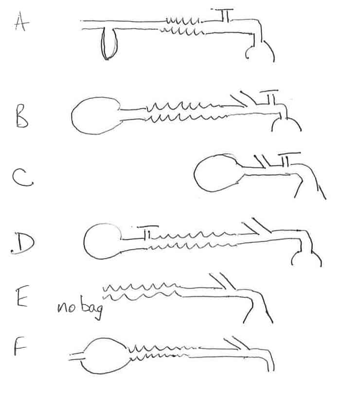
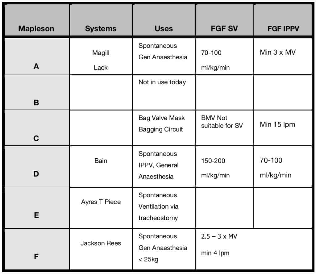
Now that we understand and can calculate the MV we will set the FGF to a particular rate depending on the breathing circuit and the MV of the patient. Professor Mapelson classified breathing circuits A-F in 1950s. It is the mainstay classification of breathing circuits to this day. When you hear the term pass me a C-circuit – the individual is referring to Professor Mapelson’s C classified breathing circuit.
The table below details the classification, systems, uses and FGF required for both spontaneous ventilation (SV) and intermittent positive pressure ventilation (IPPV).
Mapleson Classification
Reference – Introduction to Breathing Circuits. AnaesthesiaUK, 2017
Bag Mask Ventilation through an Ambu/Resuscitation Bag
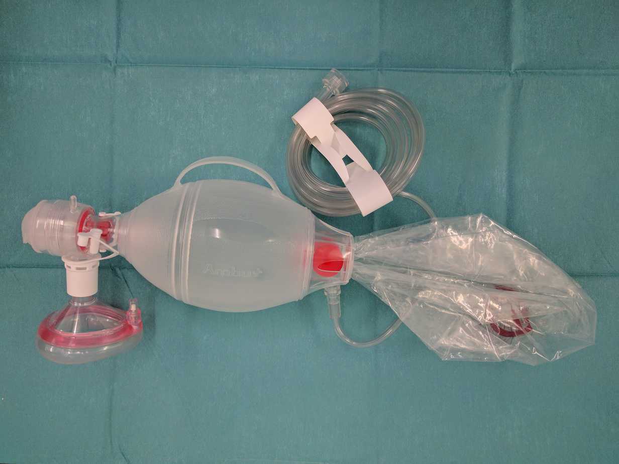
When no gas flow is present at the resuscitation e.g. gas supply failure in a hospital or out in the field, a self inflating ambu bag enables ventilation of the patient with no need for fresh gas flow to be present. This ensures room air at the very least can be delivered to the patient until an alternative gas flow can be established i.e. through an oxygen cylinder. It’s important to remember that Ambu bags have a fish mouth valve system that must be overcome with positive pressure for the valve to open. This is achieved by simply squeezing the Ambu bag which creates approximately 20cmH₂O pressure. So any healthcare practitioner must remember to synchronise squeezing the ambu bag with the patients own respiratory if they wish to support a spontaneously breathing patient.
Key Points
- Breathing circuits carry oxygen and fresh gases to the patient via an airway – face mask, LMA or ETT.
- Breathing circuits carry alveolar gases ventilated from the patient to the atmosphere.
- Breathing circuits have an inspiratory limb, an expiratory limb, a rebreathing bag, 15mm and 22mm connectors.
- The arrangement of these various components of the breathing circuit was classified by Professor Mapleson.
- The Mapleson classification determines what FGF is required to prevent a patient rebreathing carbon dioxide according to their minute ventilation.
- If the FGF supply fails or is unavailable a self inflating Ambu bag can deliver room air to the patient.
![]()
